This project started life as C routines for characterizing random pore network geometry and measuring things like concentration as a function of distance. The port to java was pretty straightforward. An interesting add-on is an MICP simulator that works by first flood-filling a Euclidean distance map of resolved pores and then continues the flood by using voxel gray level as a proxy for porosity. This page gives a basic description of the methods in the DistanceMap library. All methods support asymmetric pixels/voxel sizes and physical dimensions. DistanceMapLib.jar is available for download here. Please refer to the javadocs for a detailed description of the methods in the library. See the ImageJ plugins pages for examples.
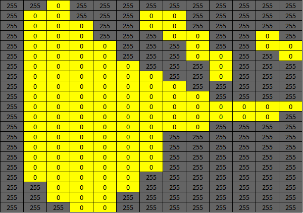
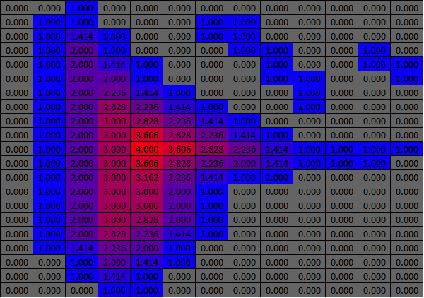
In a segmented image, ExactEuclideanDistanceMap calculates the shortest distance between each pixel in component "A" to its nearest connected neighbor in component "B" using Danielsson's algorithm. In this implementation the input image must have one component set to zero. The EDM is calculated in either the zero or non-zero component as selected by the user. To improve performance, I have done a few optimizations on Danielsson’s original 2D algorithm and extended those to 3D.

Voxels within a Euclidean sphere of radius R are defined on a Cartesian grid as √(x2+y2+z2) < R. Euclidean spheres can be used to restore a 3D shape from its medial surface (thinning the medial surface to a medial axis is a lossy process and is not reversible by sphere drawing). Euclidean spheres are also useful in constructing random porous media.
In a segmented image, this GDT calculates the shortest distance between seed pixel locations in component “A” and all other connected component “A” pixels in the image using a “brushfire” algorithm. This propagates the local shortest distance in a pixel’s touching neighbors. As such, it is limited to the directions a shortest path can take, e.g. in 2D only left, right, forward, back and 45° turns are allowed. This results in a distance over-estimate of up to 8% in non-cardinal directions that can be problematic when computing distances from point seeds over long distances. This GDT supports seeds at single and multiple points, 2D image edges and 3D volume surfaces. Distance errors are usually small when propagating from edges or surfaces.

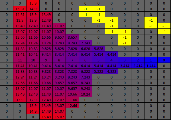
This method finds the shortest distance between a selected point or points in a geodesic image and the nearest seed point or surface.
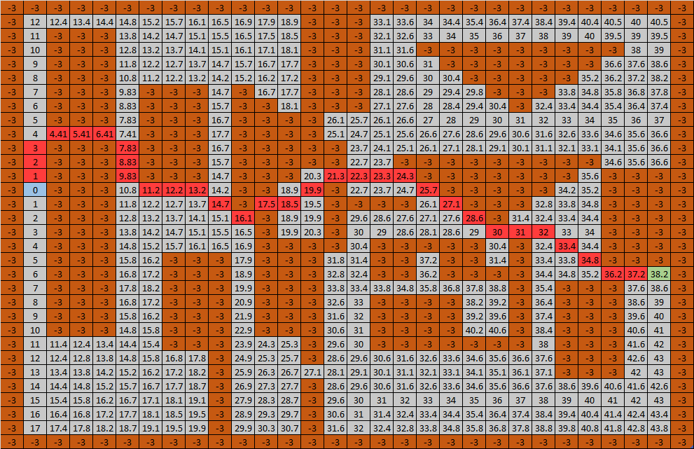
It is useful to think of hybrid flooding as a simplified method for simulating non-wetting invasion of a random porous medium. It is analogous to mercury injection capillary pressure (MICP) measurements of porous materials. In MICP a porous sample that is not wet by mercury is placed in a mercury filled pressure vessel. Initially, due to the high interfacial surface tension, the mercury does not invade the porous sample. When sufficient external pressure is applied, the mercury surface begins to bulge into the sample’s largest exposed pores. As more pressure is applied to overcome the surface tension, the mercury bulges into ever smaller pores. MICP records the volume of mercury injected at each pressure. The derivative of the resulting P-V curve is sometimes interpreted as a pore size distribution.
3D images usually do not have sufficient definition (size and resolution) to capture the range of pore and throat sizes in many random porous materials. To get around this limitation, the hybrid flood fill method must be applied to a pre-processed image where the porosity has been broken into two parts, resolved (all voxels are 1) and unresolved porosity (voxel values are less than 1 and greater than zero). It is important to use a system of length units where the voxel width, height, and depth are all greater than 1. If the voxel dimensions are less than 1 calculated resolved pore diameters may overlap values of unresolved pores.
HybridFloodFill takes the pre-processed image and a flood cutoff length as arguments and simulates a single pressure measurement in MICP by flooding the image from the top slice toward the back slice. First, the resolved pore space is converted to length measurements using an EDM. This is followed by a conventional gray scale flood up to the cutoff value. Cutoff values >1 flood only resolved pores connected to the top slice. The curved flood surface is reconstructed by drawing Euclidean spheres of the current flood radius at each point along the flood surface. The flooded voxels are counted and the flooded volume and the flooded image are returned in the report.
Cutoff values < 1 flood all connected resolved pores and unresolved pores up to the cutoff value. In unresolved pores, the porosity is used as a proxy for length*. The resolved (fully flooded), unresolved (partially flooded) voxel volumes, are returned in the report. If the flood has reached the back slice (breakthrough) an estimated tortuosity is also reported.
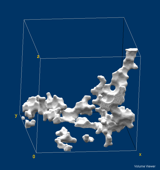
* The hybrid floodfill code was originally written to test this hypothesis. Initial results were encouraging with behavior consistent within mineral types. Other uses have included the study of mixed porosity carbonates.